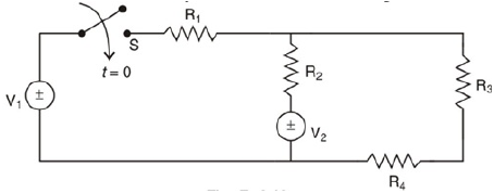
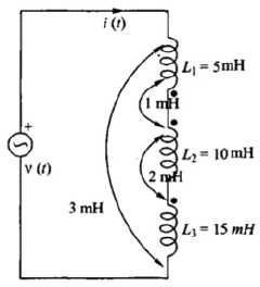
Q.1
14 MarksAlso asked in Summer 2026 Q2b

Noted. This paper is in our queue now. Check back tomorrow.
We could not record that here. Email the paper name to hirenjsca@gmail.com and we will add it.
1 of 25 questions on this paper were also asked in other years. Each is marked below with the years it appeared.See all 1 repeated BE03009031 questions, most asked first
Also asked in Summer 2026 Q2b

Explain the concept of transient and steady-state response in an RL circuit with the help of a neat sketch.

Also, discuss its key features with the help of a sketch.
Include the governing equations and a neat sketch for each response.
Analyse how the Laplace Transform simplifies the process of solving differential equations in electrical circuits. Explain how this approach helps in determining the total response of the system.
Explain the concept of poles and zeros of a transfer function. How do their locations in the s-plane influence the stability and transient response of an electrical circuit? Illustrate your answer with a suitable example.
A series RLC circuit has R=10 Ω, L=0.1 H, and C=100 μF. It is excited by a DC step voltage of 50 V applied at t=0. Derive the differential equation governing the current i(t). Find the damping factor (α) and undamped natural frequency (ω₀). Determine the nature of the transient response (overdamped, underdamped, or critically damped). Sketch and analyse the expected shape of the current response i(t) over time, commenting on transient and steady-state behavior.
A system is represented by the transfer function
Explain the Initial Value Theorem (IVT) and Final Value Theorem (FVT) of the Laplace Transform. Derive the expressions for both and discuss their significance in analysing circuit responses. Provide one example for illustration.
A series RL circuit has R=20 Ω and L=0.5 H. A DC step voltage of 10 V is applied at t=0. Derive the differential equation for the current i(t). Solve the equation to find the time-domain response i(t). Analyse the transient and steady-state behaviour of the circuit. Determine the time constant of the circuit.
What is the significance of the s-domain equivalent of circuit elements? Explain how representing resistors, inductors, and capacitors in the s-domain helps in solving circuit differential equations. Give one simple example.
Explain the significance of the transmission (ABCD) parameters of a two-port network. How can these parameters be used to analyse the cascade connection of two two-port networks? Provide a simple illustrative example.
Given the series RL circuit with R=2Ω and L=1H, and a step input V(t)=10u(t)V, use Laplace transform to determine: 1. The s-domain equivalent circuit. 2. The Laplace transform of the current I(s). 3. The time-domain response i(t). Also, analyse the transient and steady-state behavior from the obtained response.
Explain the concept of a transfer function. How can it be used to determine the output of a circuit for any given input? Illustrate your explanation with a simple example.
Explain the concept of a two-port network and its practical significance. Choose any one type of two-port parameter (e.g., Z-parameter or Y-parameter) and describe how it relates the input and output voltages and currents of the network. Give a simple example.
A series RLC circuit has R=4 Ω, L=1 H, and C=0.25 F. A step voltage V(t)=12u(t) V is applied. Using Laplace transform: 1. Determine the s-domain equivalent circuit. 2. Find the Laplace transform of the capacitor voltage VC(s). 3. Obtain the time-domain response vC(t). 4. Analyse whether the circuit is overdamped, underdamped, or critically damped, and explain the transient behaviour.
Compare Z-parameters and Y-parameters of a two-port network. Which type of parameter is more suitable for networks connected in series and which for networks connected in parallel? Justify your answer.
A two-port network can be represented by Z-parameters, Y-parameters, or ABCD parameters. Evaluate the advantages and disadvantages of using each type of parameter in practical circuit analysis.
A series R–L circuit has R=20 Ω and L=0.2 H connected to a sinusoidal voltage source v(t)=50sin(200t) V. 1. Explain how the circuit can be represented in the phasor domain. 2. Determine the phasor current in the circuit. 3. Explain how the sinusoidal steady-state voltage across the inductor can be obtained from the phasor current.
Evaluate the advantages and limitations of using transmission (ABCD) parameters for representing long-distance communication or power transmission networks. Justify your evaluation.
Evaluate the advantages of using two-port network parameters for analyzing complex electrical circuits instead of directly applying Kirchhoff’s laws. Justify your answer with practical examples.
Transform a simple series R–C circuit (R = 10 Ω, C = 100 μF) with a sinusoidal voltage source v(t)=10sin(100t) into its phasor equivalent. Determine the phasor current and explain how the sinusoidal steady-state response of the circuit can be obtained from it.
Questions repeat across sessions. Working through two or three papers shows you which topics GTU asks most.
BE Electrical
Send this paper to your class group. Every question has its own link.
Official Gujarat Technological University (GTU) examination paper for Electrical Circuit Analysis (Winter 2025, B.E. · Electrical Engineering, Sem 3). Features complete 70-mark regular & remedial examination pattern, official marking distribution across all 5 questions, and direct 1-click official PDF download.
Transcribed for student exam preparation from Gujarat Technological University official examination archives. Questions, syllabus guidelines, and curriculum marking schemes remain the intellectual property of Gujarat Technological University.
BE03009031 Electrical Circuit Analysis
Official GTU PDF · Winter 2025
The PDF could not be loaded from the university's website.
Open the PDF directly