Gujarat Technological UniversitySummer 2026 examination

GTU 3130906 Electrical Circuit Analysis Summer 2026 Solved Paper & Solutions

B.E. · Electrical Engineering · Semester 3 · Subject code 3130906
Download official PDFView PDF here
Share with your class
Total
70 marks
To pass
23 marks (33%)
Duration
2.5 Hours 2:30 PM – 5:00 PM
Questions
5 with internal choice
25 step by step solutions on this page

Q.1

14 Marks
(a)
3 marks
State Thevenin and Norton theorem.
(b)
4 marks

Discuss short-circuit admittance parameters and draw equivalent circuit for short circuit admittance parameters.

(c)
7 marks

In the network shown in fig.1, contains two voltage sources V1 and V2. With V1=30∠00 V, Calculate V2 such that the current in the 2+j3 Ω impedance is zero.
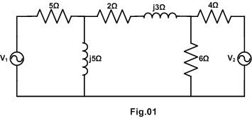
GTU Electrical Circuit Analysis (3130906) Summer 2026 Question 1(c) Diagram

Q.2

14 Marks
(a)
3 marks

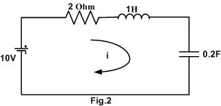
In the circuit shown in fig.2, a dc voltage suddenly applied to a series circuit. The inductor and capacitor are initially uncharged. Determine the particular solution for current i(t) in the circuit.

GTU Electrical Circuit Analysis (3130906) Summer 2026 Question 2(a) Diagram
(b)
4 marks

Describe maximum power transfer theorem and write different conditions for maximum power transfer theorem for AC circuits.

(c)
7 marks
Explain Superposition theorem with suitable example.
(c)
7 marks
Explain Reciprocity theorem with suitable example.

Q.3

14 Marks
(a)
3 marks
Elaborate series-paralle1 connection for two-port network.
(b)
4 marks

Define Kirchhoff Voltage Law and Kirchhoff Current Law with suitable example.

(c)
7 marks

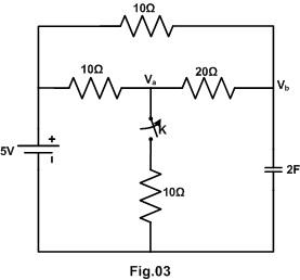
In the network shown in fig.3, a steady state is reached with the switch k open. At time t=0. Switch k is closed. For the element values given, Figure out the values Va(0-) and Va(0+).

GTU Electrical Circuit Analysis (3130906) Summer 2026 Question 3(c) Diagram
(a)
3 marks
Explain parallel-parallel connection for two-port network.
(b)
4 marks

List difference between ideal and practical voltage source and Describe about source transformation.

(c)
7 marks

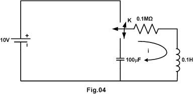
In the network shown in fig.4, the switch k is moved from position 1 to 2 at t=0 a steady state having previously been attained. Find out d²i/dt²(0+) at t=0+.

GTU Electrical Circuit Analysis (3130906) Summer 2026 Question 3 OR (c) Diagram

Q.4

14 Marks
(a)
3 marks
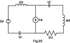
Explore the dual of the network shown in Fig.5.
GTU Electrical Circuit Analysis (3130906) Summer 2026 Question 4(a) Diagram
(b)
4 marks

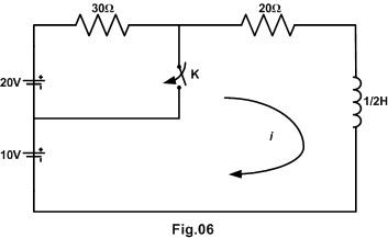
In the network shown in fig.6, a steady state is reached with the switch k open. At t=0 the switch k is closed, Compute i(t) for the numerical values given.

GTU Electrical Circuit Analysis (3130906) Summer 2026 Question 4(b) Diagram
(c)
7 marks

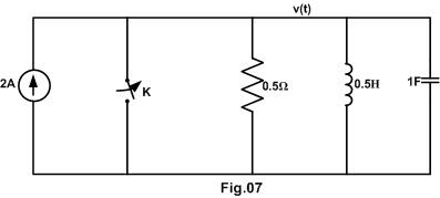
In the network of fig.7, the switch k is opened at time t=0. Evaluate the particular solution for voltage v(t) across the parallel circuit using Laplace transformation. Assume that there is no charge across the capacitor C and no current in the inductor L before switching.

GTU Electrical Circuit Analysis (3130906) Summer 2026 Question 4(c) Diagram
(a)
3 marks

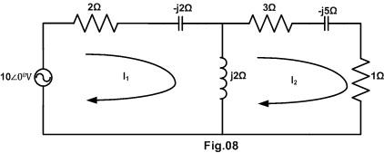
In the two mesh network shown in fig.8, Identify the mesh currents I1 and I2.

GTU Electrical Circuit Analysis (3130906) Summer 2026 Question 4 OR (a) Diagram
(b)
4 marks

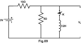
In the network shown in fig.9, the network attains a steady state, and at t=0, the switch is closed. Calculate Va(t) for t≥0.

GTU Electrical Circuit Analysis (3130906) Summer 2026 Question 4 OR (b) Diagram
(c)
7 marks

In a series R-L-C circuit, R=5Ω, L=1H and C=0.25 F and v(t) = 8e-2t Volts. Switch k is closed at time t=0. Evaluate particular solution for the current using Laplace transform method. Assume zero initial conditions in the elements.

Q.5

14 Marks
(a)
3 marks
Find out reciprocity condition for g-Parameters.
(b)
4 marks
Generalize relationship of h-parameter to z-parameters.
(c)
7 marks

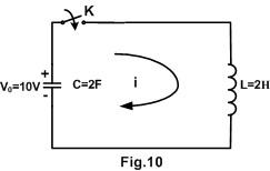
For the network shown in fig.10, the switch k is closed at time t=0. . Capacitor C is initially charged to V0 volts. Using Laplace transformation method, discover the expression for the current i(t).

GTU Electrical Circuit Analysis (3130906) Summer 2026 Question 5(c) Diagram
(a)
3 marks
Find out symmetry condition for inverse ABCD-parameters
(b)
4 marks
Generalize relationship of ABCD-parameters to y-parameters.
(c)
7 marks

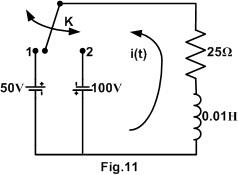
In R-L circuit shown in fig.11, the switch is in position 1 long enough to establish steady state conditions and at t=0 is switched to position 2. Discover the expression for the current in the circuit using Laplace transform.

GTU Electrical Circuit Analysis (3130906) Summer 2026 Question 5 OR (c) Diagram

Preparing with friends?

Send this paper to your class group. Every question has its own link.

About this paper

Official Gujarat Technological University (GTU) examination paper and step-by-step solutions for Electrical Circuit Analysis (Summer 2026, B.E. · Electrical Engineering, Sem 3). Features complete 70-mark regular & remedial examination pattern, official marking distribution across all 5 questions, and direct 1-click official PDF download.

Transcribed for student exam preparation from Gujarat Technological University official examination archives. Questions, syllabus guidelines, and curriculum marking schemes remain the intellectual property of Gujarat Technological University.

ViewDownload PDF