Gujarat Technological UniversityWinter 2024 examination

GTU 3150911 Power System- II Winter 2024 Question Paper & PDF

B.E. · Electrical Engineering · Semester 5 · Subject code 3150911
Download official PDFView PDF here
Share with your class
Total
70 marks
To pass
23 marks (33%)
Duration
2.5 Hours 10:30 AM – 1:00 PM
Questions
5 with internal choice
No solutions on this paper yetNeed them for your exam? Ask once. Papers that students ask for are solved first, and we aim to add them within 24 hours.

Q.1

14 Marks
(a)
3 marks

What is meant by three-phase balanced circuit? Write down expressions of three- phase balanced voltage phasors in polar form.

(b)
4 marks

With the help of phasor diagram for π-model of the transmission line, show that the receiving-end voltage magnitude becomes greater than the sending-end voltage magnitude when the transmission line is under no-load condition. What is the name of this effect?

(c)
7 marks

Compare nominal-T and nominal-π method for analysis of medium transmission line with phasor diagrams and necessary expressions.
Q.2

14 Marks
(a)
3 marks
Evaluate percentage voltage regulation of a medium line that has the following parameters: A=0.95∠1°A = 0.95\angle 1°, B=100∠75° ΩB = 100\angle 75°\ \Omega. The receiving-end and sending-end voltage magnitudes are found to be ∣VR∣=132 kV|V_R| = 132\ \text{kV} and ∣VS∣=139 kV|V_S| = 139\ \text{kV} respectively when the transmission line delivers a typical load.
(b)
4 marks

Show the steps to draw the receiving-end circle diagram to obtain the sending-end voltage magnitude and angle.

(c)
7 marks

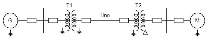
Create per unit reactance diagram for the power system shown in Fig.-1. Start with base MVA of 100 and base kV of 220 in 50Ω line. The ratings of components are: Generator: 40 MVA, 25 kV, X=20% Motor: 50 MVA, 11 kV, X=30% T1: 40 MVA, 33/220 kV (Y-Y), X=15% T2: 30 MVA, 11/220 kV (∆-Y), X=15% Line: Inductive reactance of 50Ω

GTU Power System- II (3150911) Winter 2024 Question 2(c) Diagram
(c)
7 marks

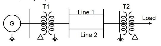
Create per unit impedance diagram for the sample power system shown in Fig.-2. Start with base MVA of 100 and base kV of 10 in generator circuit. The ratings of components are: Generator: 100 MVA, 10 kV, X=j0.5 pu T1: 3-phase, 2-winding, delta-star transformer developed by using three single-phase units, each single-phase unit rated 35 MVA, 10/230 kV, X=j0.1 pu. T2: 90 MVA, 400/10 kV (Y-∆), X=j0.1 pu Line 1 and Line 2: Inductive reactance of each line 200Ω. Load: Impedance of (0.1+j0.5) Ω.

GTU Power System- II (3150911) Winter 2024 Question 2 OR (c) Diagram

Q.3

14 Marks
(a)
3 marks

How many symmetrical components are required to analyze 12-phase unbalanced system? What will be the sequence operator in that case?

(b)
4 marks

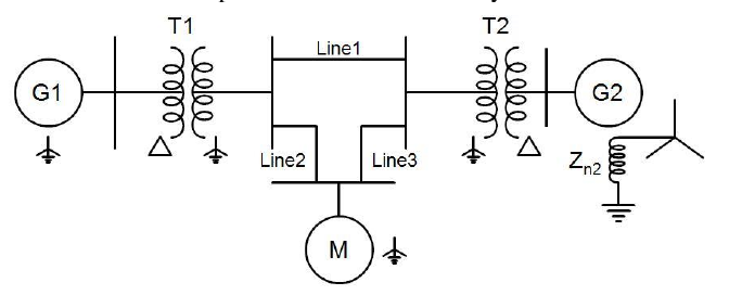
Draw zero sequence network of the power system shown in Fig.-3. The transformers and lines are to be represented as reactance only.

GTU Power System- II (3150911) Winter 2024 Question 3(b) Diagram
(c)
7 marks

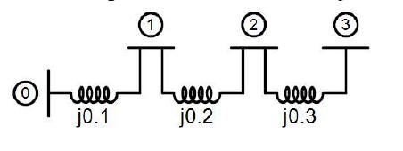
Formulate Zbus using step-by-step algorithm for symmetrical fault analysis in case of the power network shown in Fig.-4. The reactances are in per unit.

GTU Power System- II (3150911) Winter 2024 Question 3(c) Diagram
(a)
3 marks

Express three-phase unbalanced current phasors in terms of sequence components in matrix form using sequence operator.

(b)
4 marks

A balanced delta-connected load is connected to a three-phase supply and is supplied line current of 15 A. If the line ‘b’ is opened suddenly, compute symmetrical components Ia1, Ia2 and Ia0 of the line current.

(c)
7 marks
Analyze behavior of short circuit current with relevant expression and waveforms when a three-phase short circuit occurs suddenly at the end of a transmission line being fed from constant voltage source v=Vmsin⁡(ωt+ψ)v = V_m \sin(\omega t + \psi) V. Assume that the line is represented as series impedance Z=(R+jXL) ΩZ = (R + jX_L)\ \Omega and the fault occurs at t=0t = 0. Line charging capacitance is neglected.

Q.4

14 Marks
(a)
3 marks

Why is the zero sequence impedance of the transmission line approximately 2.5 times the positive sequence?

(b)
4 marks

Prove that the fault current is given by the following expression when an LL (line-to-line) fault takes place between terminals “b” and “c” of an unloaded synchronous generator through ZfZ^f:

If=−j3 EaZ1+Z2+ZfI^f = \frac{-j\sqrt{3}\,E_a}{Z_1 + Z_2 + Z^f}
where notations have their usual meaning.

(c)
7 marks
A three-phase, 6.9 kV, 10 MVA alternator has X′′=X2=15%X'' = X_2 = 15\% and X0=5%X_0 = 5\%. The neutral is grounded through an inductive reactance of 0.381 Ω. Evaluate the subtransient current in ampere in the faulted phase, when a single line to ground fault takes place on phase-a.
(a)
3 marks

Draw single-phase model of positive, negative and zero sequence network of a three- phase synchronous generator whose star-point of stator winding is connected to ground through Zn.

(b)
4 marks

Sketch interconnection of sequence networks for single line to ground fault with equations of sequence currents and fault current.

(c)
7 marks

A power system has equivalent positive, negative and zero sequence impedance of j0.2243 pu, j0.1741 pu and j0.15 pu respectively. Evaluate per unit positive sequence current, zero sequence current and fault current if a solid LLG (line-to-line-to-ground) fault is to be simulated.

Q.5

14 Marks
(a)
3 marks

Write down corona loss formula given by Peek on basis of weather conditions and name each of the parameters in the expression.

(b)
4 marks
Compare protection provided against lightning by earthing screen and ground wires.
(c)
7 marks
Voltage and current travelling waves passing through line having surge impedance Zc1Z_{c1} arrive at discontinuity point from where another line having surge impedance Zc2Z_{c2} starts. For this configuration, derive ratio of (i) the reflected voltage wave to incident voltage wave and (ii) the transmitted (refracted) voltage wave to incident voltage wave with usual notations.
(a)
3 marks
What will be the effect of the following on disruptive critical voltage and corona? (i) increasing diameter (ii) reducing spacing between conductors (iii) rise in barometric pressure of air
(b)
4 marks
Differentiate between direct and indirect lightning strokes.
(c)
7 marks
A line is terminated with (i) short circuit and (ii) open circuit. In these two cases, show by waveforms how voltage and current travelling waves move with time and distance. Assume rectangular wave shape of the waves.

More Power System- II papers

Questions repeat across sessions. Working through two or three papers shows you which topics GTU asks most.

Preparing with friends?

Send this paper to your class group. Every question has its own link.

About this paper

Official Gujarat Technological University (GTU) examination paper for Power System- II (Winter 2024, B.E. · Electrical Engineering, Sem 5). Features complete 70-mark regular & remedial examination pattern, official marking distribution across all 5 questions, and direct 1-click official PDF download.

Transcribed for student exam preparation from Gujarat Technological University official examination archives. Questions, syllabus guidelines, and curriculum marking schemes remain the intellectual property of Gujarat Technological University.

ViewDownload PDF