Question 1
Define ideal current and ideal voltage source. State the difference between an Ideal and practical voltage source.
A single-phase R–L circuit has R=10 Ω, L=0.1 H, supplied by 230 V, 50 Hz. Calculate current, inductive reactance and impedance.
Explain the construction and working of a three-phase induction motor with neat diagram. Also state the role of slip in its operation.
Explain the construction and working of a single-phase induction motor with neat diagram. Why is it not self-starting?
Compare mesh analysis with nodal analysis. Analyze which method is more suitable for circuits with more voltage sources.
Two RL circuits have the same inductance but different resistances: Circuit A: R=2 Ω, Circuit B: R=10 Ω. Compare their time constants. Analyze which circuit responds faster and justify.
Derive condition XL=XC in series RLC resonance. Explain why impedance is minimum. Draw and analyze: variation of current vs frequency, variation of impedance vs frequency, Identify resonance point.
Identify the primary difference between a step-up and a step-down transformer in terms of their turn ratios. State which winding (primary or secondary) has thicker wire in a step-down transformer.
A balanced 3-phase, 3-wire load is supplied with a line voltage of 400 V. The readings of two wattmeter connected by the two-wattmeter method are: W1=5 kW, W2=1 kW. Determine: Power factor of the load, Nature of power factor (lagging or leading), Phase angle of the load.
A balanced load is connected first in star and then in delta across the same supply. Compare line current in both cases. Analyze power consumption in both connections.
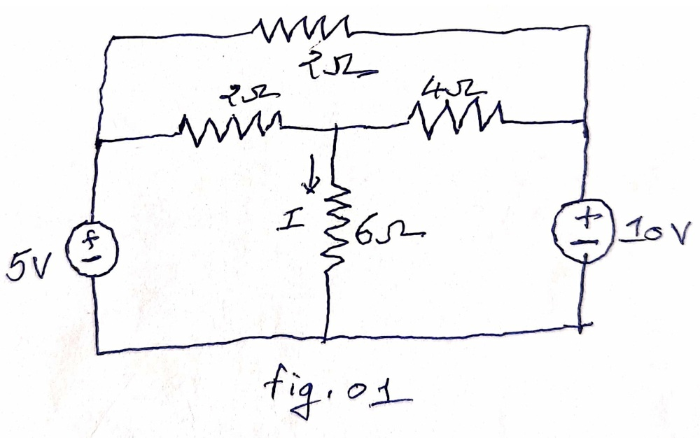
Using the Superposition Theorem, find the current through the 6 Ω resistor in the given circuit.

Explain autotransformer in brief and describe the primary structural difference between the autotransformer and normal transformer.
A balanced star-connected load has: VL=400 V, Zph=10+j5 Ω. Calculate phase voltage, phase and line current, power factor, total power.
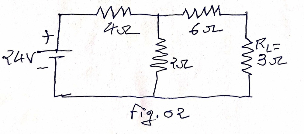
Using Thevenin’s Theorem, find the current through the load resistor RL=3 Ω for the given circuit.

Circulate this solved paper with KaTeX formulas and 1-click AI step solvers to your batchmates on WhatsApp or Telegram.
Official Gujarat Technological University (GTU) examination paper and step-by-step solutions for Basic Electrical Engineering (BEE) (Summer 2026, B.E. · Common Engineering, Sem 1). Features complete 70-mark regular & remedial examination pattern, official marking distribution across all 5 questions, and direct 1-click official PDF download.
Transcribed for student exam preparation from Gujarat Technological University official examination archives. Questions, syllabus guidelines, and curriculum marking schemes remain the intellectual property of Gujarat Technological University.